36V or 48V Systems
Cabin Heater
Overview
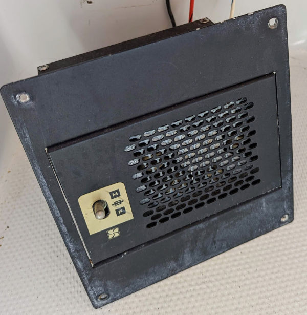
Our boat has two flush-mounted cabin heaters that appear to be custom built for the Duffy. They are powered when the key switch is on and have a local toggle switch to select the mode of operation (Heat/Off/Fan).
Hazards
- A single 12V contactor switches the +36V supply to both heaters. It is not designed or rated to switch the heaters on, only the toggle switch is. If one or both toggle switches are in the "Heat" position when the key switch is turned on, the 12V contactor will be switching 36V of high current (approximately 17A inrush current to each heater). For this reason, it is important to ensure that heater toggle switches are in the "off" position before turning the key switch on.
- In-line fuses for the 36V heating elements and 12V fans on our boat were improperly sized, allowing too much current to be drawn and wiring to burn. These fuses are located near each heater's wiring connections. The 36V circuit draws ~15A with an initial inrush current of 16.1A.
- 36V wiring from the batteries to the contactor should also have a properly sized fuse at the battery connection to prevent the wire from overheating in the event of a short.
Design
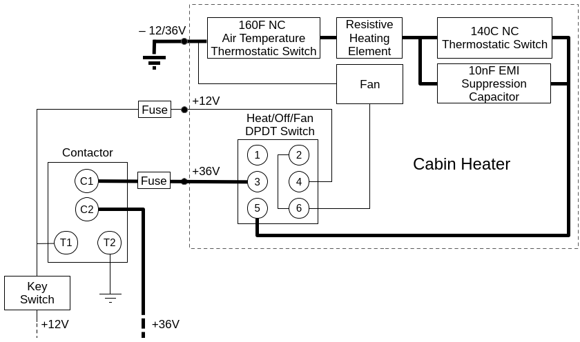
The heater has two normally closed temperature switches.
- The first switch is attached to one end of the resistive heating element where heat will conduct from the element. It opens at 140C (248F). The designer expected this to open periodically since they added a suppression capacitor. The contacts on our switch were moderately pitted.
- The second switch is located between the fan and heating element. It will open at 160F, which is a condition that would occur if the fan were to fail. This switch has a manual reset button that can only be accessed by disassembling the heater, which is OK since something would have failed internally for this switch to trip.
Components
-
140C Thermostatic Switch
The only markings on the existing switch were "140 +/- 5C" and hand written "24V"(!). The Cantherm A1014005 may be a good replacement. -
160F Air Temperature Switch
Original part: Therm-O-Disc 60T15 611213
Replacement: White Rodgers / Emerson 3L02-160 - 10nF Capacitor
Vishay 103Z 440L -
Fan
Mechatronics E9225X12B
This looks like a normal PC fan, but it operates at a higher speed (4,000 RPM) and moves a higher volume of air than a typical PC fan. -
Resistive Heating Element
This is a custom part, though the element could be rebuilt by coiling NiChrome wire with the proper resistance.
Contactor
The contactor is located in the Starboard battery compartment. When the key switch is turned on, you should hear the contactor close (a loud "clack"). When the key switch is turned off, you should hear the contactor open to its default power off, normally open, state.