12V Systems
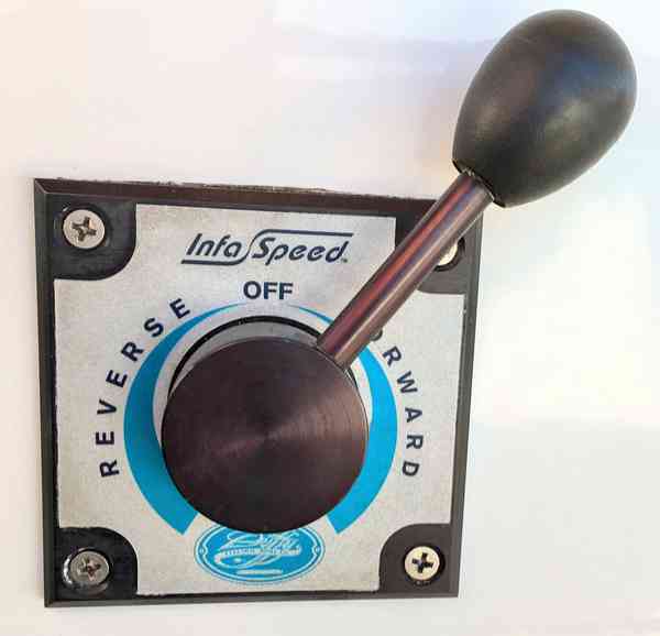
Throttle
A print-ready version of some of this information is available here.
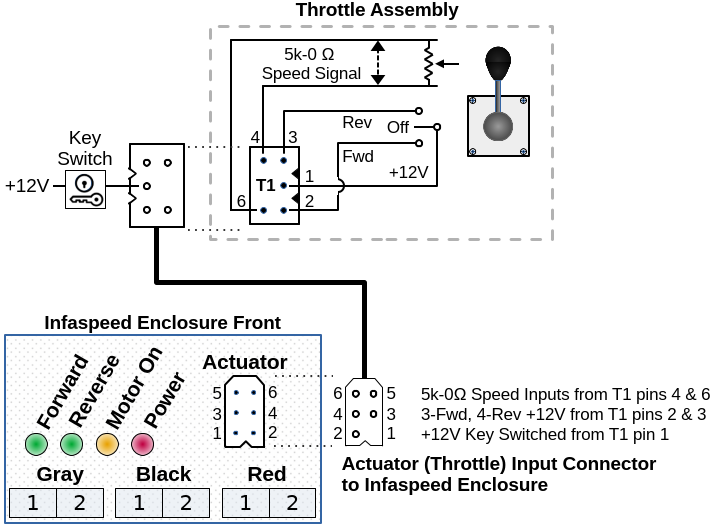
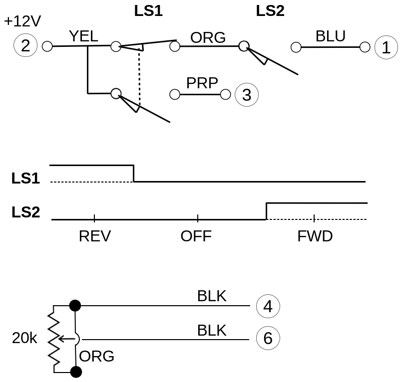
The throttle receives +12V when the key switch is on. It outputs +12V to signal forward/off/reverse state and to provide +12V to the motor controller. The throttle also provides a speed signal in the form of resistance varying between 5Ω (0% relative speed) and 0Ω (100% relative speed) in either forward or reverse. The motor controller interprets the relative speed signal to control the actual motor speed as defined by its programming. Your motor controller may require a different speed signal, such as different resistance values, but 5Ω to 0Ω is common.
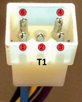
It is easiest to troubleshoot the throttle at the "Actuator" connector on the Infaspeed enclosure beneath the operator's seat. You will need to find a ground to measure the +12V inputs. There is a ground bus inside the motor compartment.
The motor controller will fail safe by stopping the motor if it does not receive a reliable or expected signal from the throttle. The most common problem is the speed signal intermittently dropping out due to a worn or corroded potentiometer in the throttle assembly.
Design
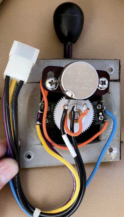
The throttle has a potentiometer that provides the 5Ω to 0Ω speed signal.
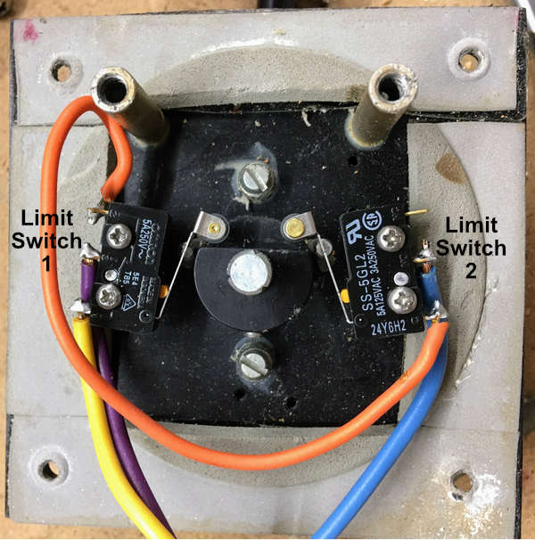
It has two SPDT limit switches triggered by a cam on the throttle lever to signal
Forward/Off/Reverse states.
Two ball nose spring plungers rest in a detent when the
throttle is in the off position and provide resistance to hold the throttle lever in other
positions.
The potentiometer shaft is turned by gears connected to the throttle lever. It is a 20k ohm potentiometer that is wired as two 10k ohm resistors in parallel for a peak resistance of 5k ohms. Resistance is highest when the throttle is centered (off) and reaches or approaches zero ohms at full throttle in either forward or reverse.
The throttle and motor controller electrical system is designed to fail-safe. If there is a loss of signal from the throttle, the motor controller will shut off the motor. If the throttle is not in the neutral position when the master switch is turned on, the motor controller will disregard the signal until the throttle is first returned to neutral.
The mechanical throttle components do not fail-safe. If the gears fail to engage while the motor is on, the throttle can only be shut off by turning off the master key switch. Once this is done, the boat will be dead in the water as the controller requires a neutral throttle position to start, which likely cannot be achieved in this condition.
Rebuilding the Throttle
Electrical Components
-
Potentiometer: The original part number is
RV4NAYSD203A.
The specifications are:- 20K Ohm
- 2W
- 10% tolerance
- 500V
- 1 turn
- 314° rotation
- Linear taper
- Switch: No
- Solder lugs
- Shaft length: 7/8" (0.875"/22.23mm)
- Shaft diameter: 1/4" (0.250"/6.35mm)
- Panel mount bushing: 3/8" (0.375"/9.53mm)
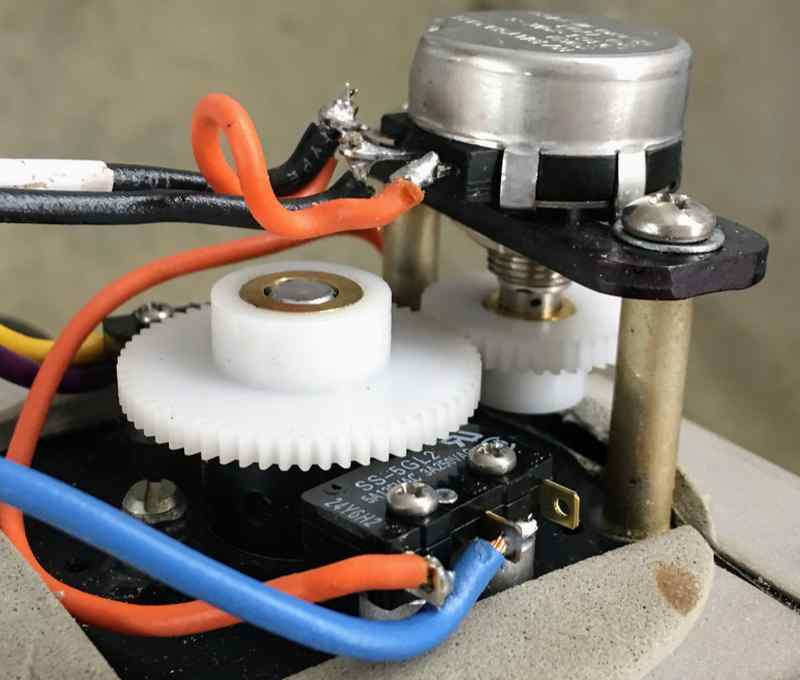
- Two switches: Omron SS-5GL2 snap action roller lever switches, SPDT, 5A, 125 VAC
Potentiometer Installation and Calibration
Adjust the potentiometer until maximum resistance is measured, then mate the potentiometer gear to the throttle lever gear while the throttle is in the "Off" position. At full throttle in either forward or reverse, you should measure near zero resistance.
Ensure that there is full movement through the 180 degree throttle travel. The throttle lever has physical stops that limit movement when at full forward or full reverse. The potentiometer should not be limiting movement - only the throttle stops.
Adjust the potentiometer position so the gears mesh properly - without binding and without being too loose. Shims may be required to properly align the gears.
Mechanical Components
-
Two slotted ball-nose spring plungers. Vlier P/N DSSB54N or Gibraltar
SSWN10-4B-G.
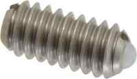
The specifications are:- Stainless Steel body
- Nylon ball
- 1/4-20 threads
- 0.125" ball diameter
- 0.531" body Length
- 0.035" maximum ball reach
- 3 lb initial end force
- 7 lb final end force
-
Two Gears, one 60 tooth and one 40 tooth.
The specifications are:- 60 tooth gear - 1.292 inch OD
- 40 tooth gear - 0.875 inch OD
- Bore: 0.25"
- 20 degree pressure angle
- 48 pitch
- Material: Acetal
www.sdp-si.com part numbers:
60 tooth gear: A1P2-Y48060
40 tooth gear: A1P2-Y48040C
Gear Specifications (PDF)
The brass bore of the 60 tooth gear needed to be slightly enlarged to accommodate the throttle lever shaft. The elongated hole on the adjustable plate also needed to be slightly lengthened.
Throttle lever travel is 180 degrees. The potentiometer has an effective travel of 270 degrees. To adjust for the different degrees of movement, the throttle lever drives a 60 tooth spur gear mated with a 40 tooth gear that rotates the potentiometer.
The original gears have the larger 60 tooth gear press-fitted directly to the throttle lever. The smaller gear has a set screw and is attached directly to the potentiometer, which has a detent drilled on the shaft. The smaller gear and potentiometer are screwed to an adjustable plate, which is shimmed with washers to enable alignment with its mating gear.
One of our gears was damaged and needed to be replaced. The specs for the original gears are unknown, so we replaced them with a matching set with the same tooth count, 1/4" bore, and approximate outside diameters.
We used machined gears with brass inserts because they were immediately available. The replacement gears each have set screws, which provide a more positive connection than the original press-fit and allow for more precise alignment of the gears.