36V or 48V Systems
Motor Controller and Contactors
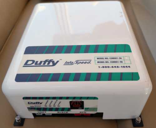
The motor controller and high voltage contactors are independently serviceable. They are housed together in an enclosure labeled "InfaSpeed" located under the operator's seat.
Infaspeed Enclosure
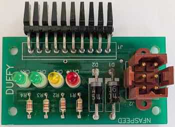
The InfaSpeed enclosure provides mount points and a cover for motor control components as well as modular electrical connections and LED indicators. In older models, the controller and contactors are independent units located in the motor compartment/operator's console.
Connections and Indicator LEDs
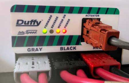
There are three 36V/48V high voltage DC connectors on the bottom that connect to the batteries and motor. The connector labled "Actuator" comes from the throttle and a 12V power source.
The LEDs indicate +12V signals coming from the "Actuator" connector.
| LED Label | LED Should Be On When | Indicates |
|---|---|---|
| Power | Key switch is on | Connections to the Infaspeed box are providing + and - 12V to the motor controller and fan. |
| Motor On | Key switch is on and throttle is in either forward or reverse | Either the forward or reverse contactor coil is receiving +12V to energize it. It does not indicate that either contactor is working properly. This LED indication is only useful if either the forward or reverse LEDs are not functioning. |
| Reverse | Key switch is on and throttle is in reverse | The reverse contactor coil is receiving +12V to energize it. It does not indicate that the contactor is working properly. |
| Forward | Key switch is on and throttle is in forward | The forward contactor coil is receiving +12V to energize it. It does not indicate that the contactor is working properly. |
When troubleshooting a problem with the propulsion system, start by checking for the proper LED indications. If that checks out, check the speed signal at the connector to the Infaspeed enclosure as described in the throttle web page. If both check-out, you know the motor controller and contactors are receiving the proper signals from the throttle, though it is difficult to measure an intermittent problem.
Note that the motor controller will fail safe if it receives an unsafe or unexpected signal.
For example, the motor controller will prevent the motor from operating if the throttle is
in either Forward or Reverse when the key switch is turned on. The throttle must first be
Off.
The contactors operate independently of the motor controller, so you will hear
them operate and you will see the LEDs light to indicate the signals they receive, but the
motor controller may not be getting the signals it needs to allow the motor to operate.
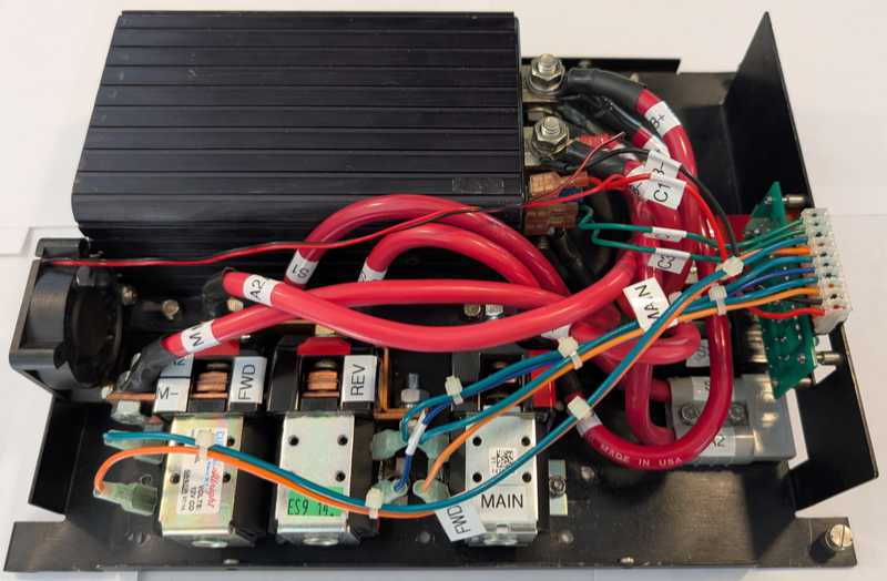
Internals
The Infaspeed enclosure contains
- Programmable Motor controller
- Main contactor
- Combination forward and reverse contactors
- Circuit board
- High voltage DC connectors
- Fan
The inside of the enclosure looks like this.
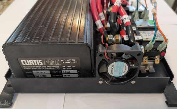
Programmable Motor Controller
The motor controller is an electronic component that serves the following general functions:
- Regulates motor speed in response to a speed signal from the throttle and to operate within programmed parameters (e.g. ramp-up/down settings).
- Provides the proper outputs to start and stop the motor
- Protects against overloads, electrical faults, and thermal extremes
- Provides safety functions (e.g. fail-safe operation, safe transition from forward to reverse modes, etc.)
Most motor controllers have programmable settings such as those listed below, though our unit doesn't have the typical programming connector.
- Acceleration rate
- Maximum motor speeds (forward and reverse)
- Throttle input type and sensitivity
- Under-voltage controls
- Current limits
Testing
The motor controller uses Pulse Width Modulation (PWM) to vary voltage to the motor in response to throttle speed signals. This occurs between motor controller terminals B– (the negative high voltage input from your batteries) and M– (the common high voltage connection between your forward/reverse contactors, which connect to the motor).
Validate that all inputs to the motor controller are as they should be. At full speed, Voltage measured between B– and M– should be close to zero. Voltage should increase between B– and M– as speed decreases.
High Voltage Contactors
Contactors use a 12V input to switch 36V/48V motor circuits. You can hear them mechanically switching (a "clack" sound) as you change throttle modes between off/forward/reverse.
These contactors are common for motor control applications and are not specific to Duffy.
There are many third-party suppliers that use the part numbers below or advertise as being compatible with these part numbers. Given the effort required to change contactors, I would not use a contactor of unknown quality.
Higher amperage contactors are available that will last longer, but they are larger and available space in the Infaspeed enclosure is tight. Check dimensions carefully.
Main Contactor
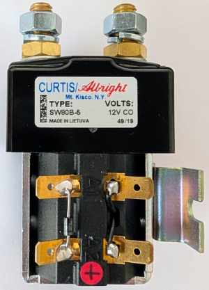
The Main contactor is normally open and closes in response to either a forward or reverse throttle direction input.
We have a Curtis/Albright SW80 with the following specifications
| Manufacturer | Curtis/Albright |
| Model | SW80 |
| Amperage | 100A |
| Coil | 12V DC Continuous |
| Coil (Surge) Suppression | Yes - This option adds a surge suppression diode across the coil terminals. See explanation below. |
| Bracket | Hat shape P/N 2126-48A. You may be able to reuse your existing bracket. |
| Blowout | Optional. If selected, the coil contacts will last longer, but it requires proper connection polarity which may differ slightly from your current installation |
Supplier:
Tecknowledgey 
Reversing Contactors
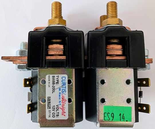
Reversing contactors swap the polarity to either the motor stator or armature to
change motor rotation. They are a pair of contactors tied together with two common buses
to allow for a more convenient installation than two separate contactors would allow.
We have a Curtis/Albright SW88 with the following specifications
| Manufacturer | Curtis/Albright |
| Model | SW88 |
| Amperage | 100A |
| Coil | 12V DC Continuous |
| Coil (Surge) Suppression | Yes - This option adds a surge suppression diode across the coil terminals. See explanation below. |
| Bracket | DC88/DC88P/SW88 Integral & Top Hat Bracket. You may be able to reuse your existing bracket. |
| Blowout | Optional. If selected, the coil contacts will last longer, but it requires proper connection polarity which may differ from your current installation |
Supplier:
Tecknowledgey
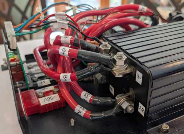
You may need to reuse your existing bus bar connecting the top front terminals as they sometimes don't ship with them, as the above picture shows.
If the motor runs in the opposite direction than expected after changing the reversing contactor, swap S1 and S2 connections on the reversing contactors.
Coil Surge Suppression Diode
A diode across the coil terminals suppresses the high voltage spike generated when the contactor coil is de-energized. Without the diode, voltage can surge to many times the rated coil voltage, which would propagate upstream to your throttle and other systems.
There are two coil connections, A1 and A2, which each have two male spade terminals. The diode is soldered to one pair of male terminals, leaving the other pair to accept female spade terminal connections, carrying the 12V input, without interference.
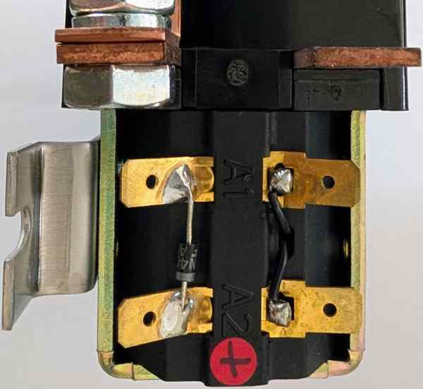
Note that adding a diode polarizes the contactor coils, so the coil will only operate with the correct +/- connections. The diode on your replacement contactor could be installed in a different orientation than your original contactor, which would require swapping the positive and negative coil connections. The diode cathode is marked with a stripe and is on the positive coil terminal.
If you need to install the diode yourself, a 1N5001 is typical.
Circuit Board
All components are generic except for a small circuit board with LEDs and the Actuator (throttle) connector. This circuit board has internal and external low voltage connectors, makes wiring cleaner, and provides non-essential diagnostic LEDs. It could be eliminated if necessary (a schematic can be found here).
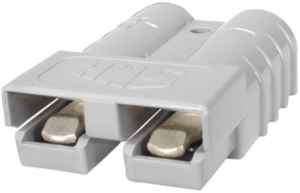
High Voltage DC Connectors
The high voltage, high current connectors on the Infaspeed enclosure and on cables connecting to it are Anderson Power Products/SMH SB175 Series Connectors. Terminals come in different sizes to fit your wire size.
Fan
The cooling fan is a Sunon KDE1205PHB2 with the following specifications:
- 12 VDC
- 50x50x15mm
- Two wire
- 4,700 RPM
- 13.0 CFM